
If you always do what youve always done, youll always get what youve always got. (Henry Ford)
Since one suspects nothing bad, popping-up naively at the regular technical inspection and emssion control test - and ?
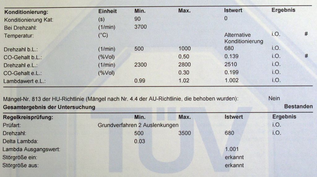
Emission control test FAILED!
The CO value at idle speed was above the limit. As if idling in a 5.6L V8 would be of interest to anyone ...
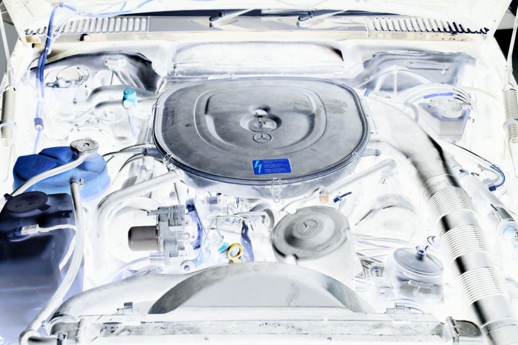
I already knew that a KE-Jetronic injection system works in my SL. Also, I knew that I have no glue.
There were two options. Either make a pilgrimage to a self-proclaimed specialist and unhiding my technical illiteracy or taking the matter into my own hands. Since my SL does not have an IP address, most workshops with their attach a computer knowledge will not be able to solve my problem. So I decided for option Be a man and face the challenge!.
As I worked more and more with my KE-Jetronic 3.1 injection system, I screwed the SL with my right hand and made my own engine diagnostic system with my left hand. How this adventure ended - well, just read on.
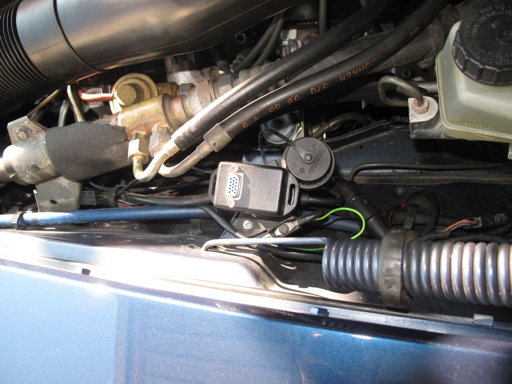
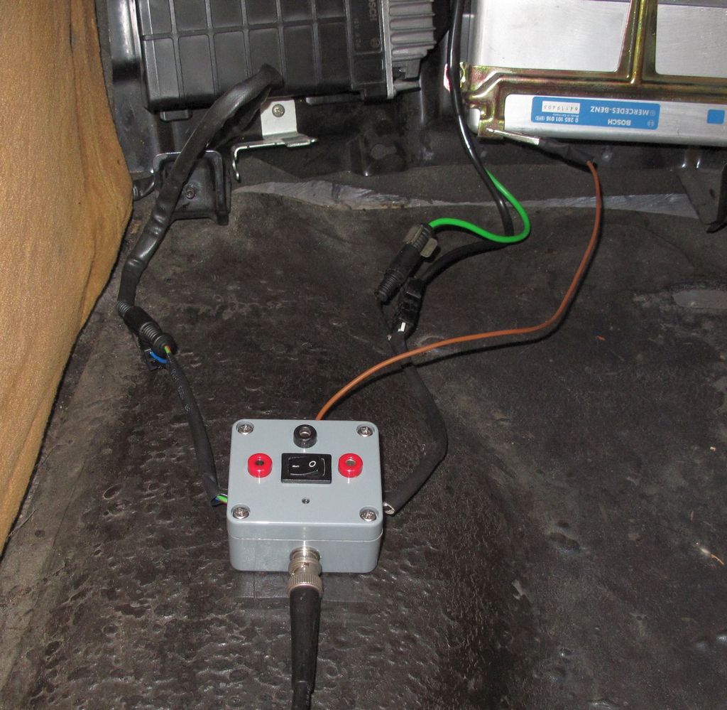
The starting point was the diagnostic socket X11 on the left side in the engine compartment. According to the instructions in the workshop manual 07.3-121 I needed the tachometer signal, the control signal from the KE control unit to the electro-hydraulic actuator (EHS), as well as the signal from the O2 sensor. Unfortunately I do not have a CO emissions tester - maybe it works without ...
First, an adapter for the X11 socket had to be tinkered, because a connector is not available for purchase anymore.
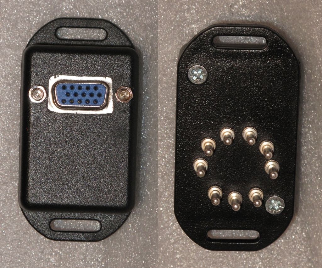
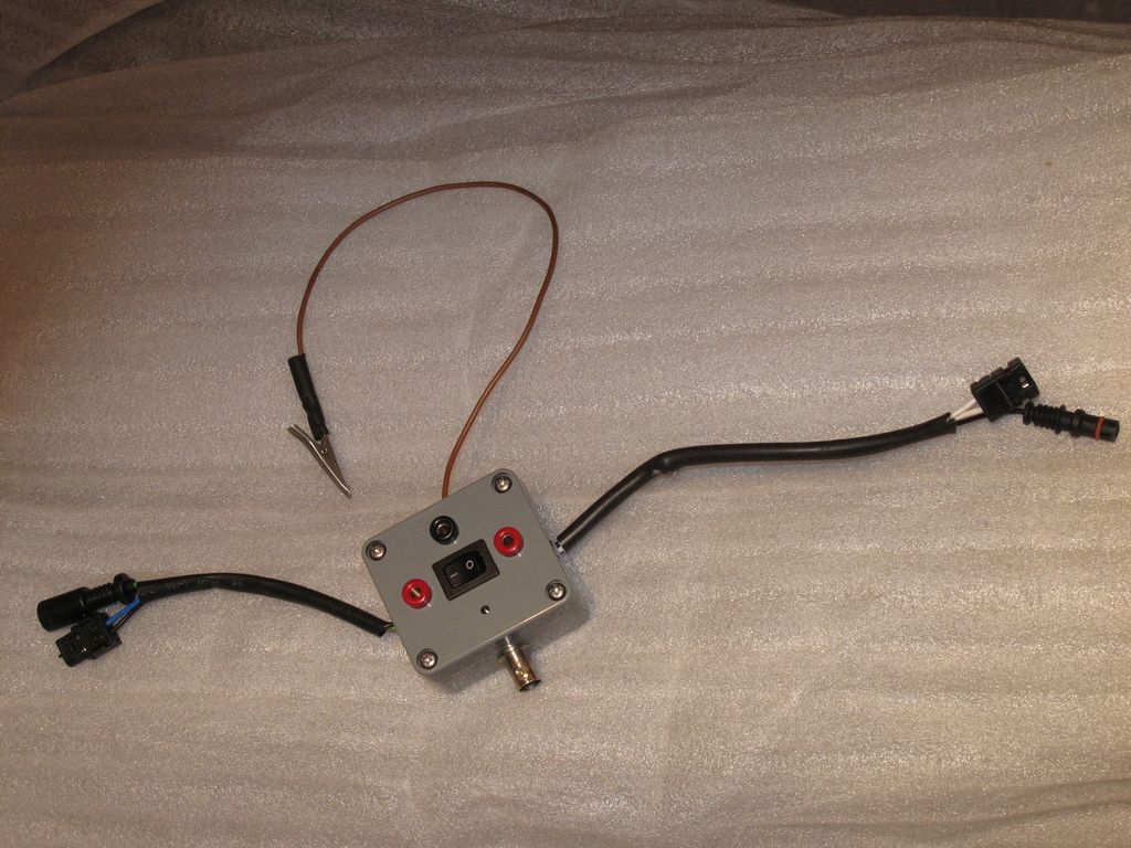
Afterward I developed an electronic box. In this box, the signal processing and pre-processing of the signals is performed. A microcontroller transmits the measured values to the PC via USB. The main challenge was the development of the analog electronics for the signal processing.
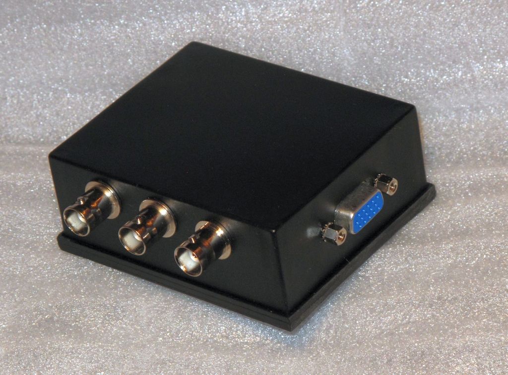
Furthermore, I needed a solution to hook up the signal from the O2 sensor. Therefore I built myself a break-out box, with which I can measure both, the probe signal as well as the voltage at - and the current through - the sensor heating.
Finally, I developed a software to display the measured values with their course, to calculate the mean value and to log the measured values in order to evaluate them with a spreadsheet program.
And btw, in a month I had to be done to keep the deadline for the emission control re-test.
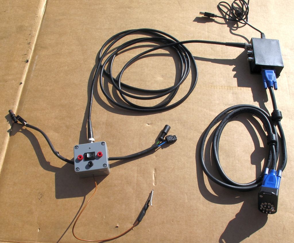
In the following pictures you can see the individual components of my diagnostic system. The video shows the values at idle speed and increased idle.
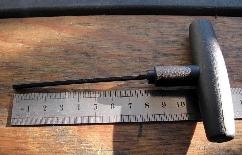
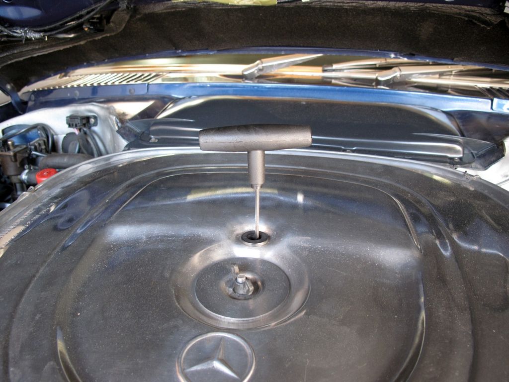
With the shown 3mm imbus key I was able to adjust my KE-Jetronic accordingly and have passed the emission control test with a lambda value of 1.002 with flying colors (Remark of the test engineer).
Well done!