
Haste makes waste.
The cruise control had not worked from the beginning. As well as another second-hand acquired cruise control module did not show the desired effect, it was now time to fully concentrate on the cruise control system .
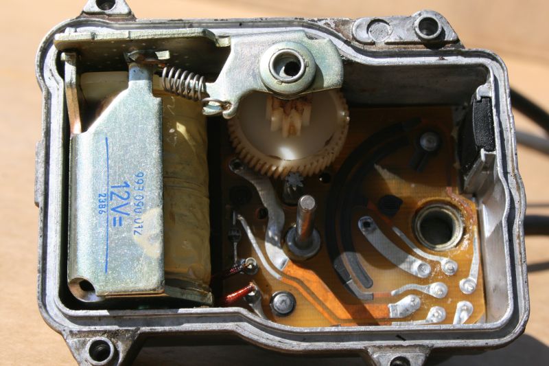
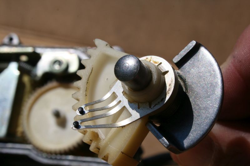
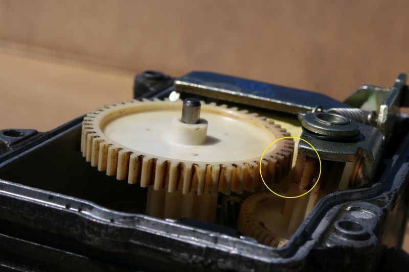
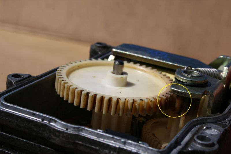
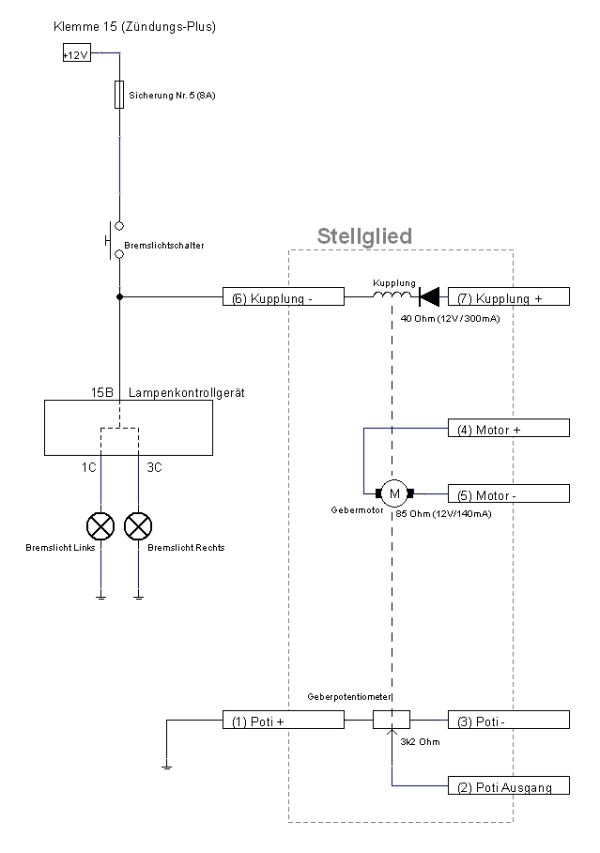
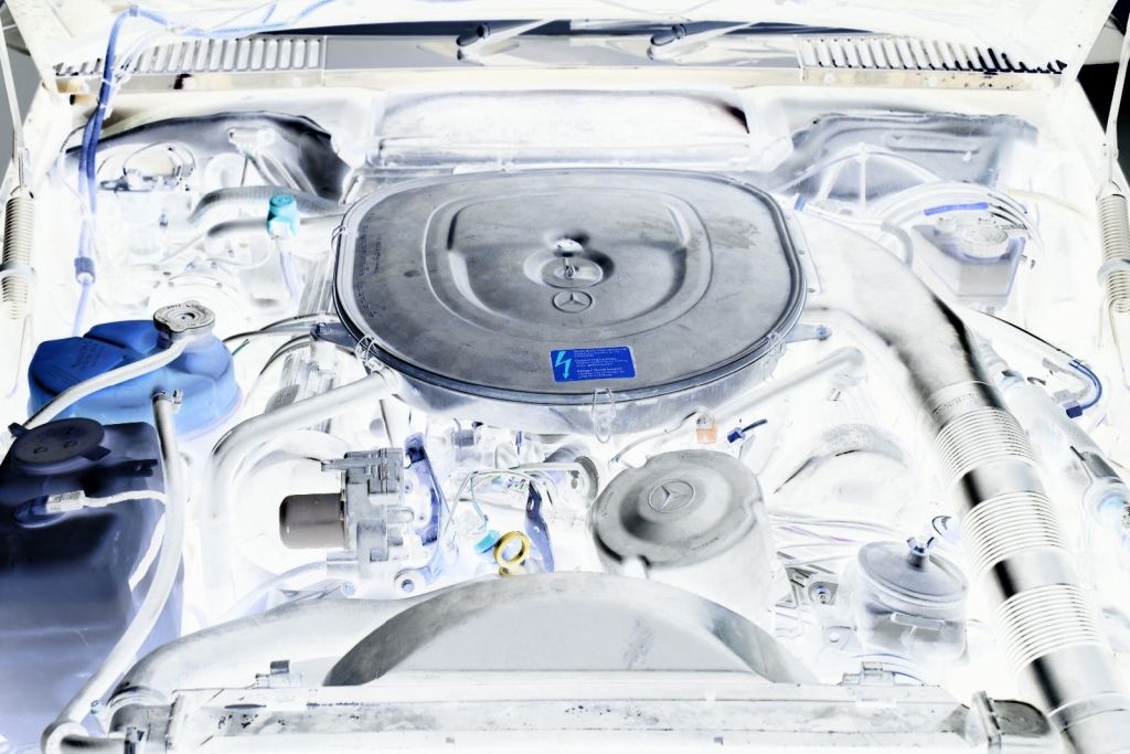
First, I have to understand the functionality of the actuator servo in the engine compartment. The actuator operates the throttle linkage. I have acquired a second-hand actuator for a few euros. Electric motor, electromagnet, potentiometer and some gears - that's all inside. In a Video (German only) and on the following pictures the function is explained.
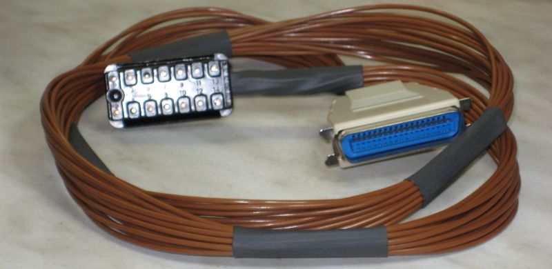
The actuator in my vehicle was working properly, so I have to investigate the other components. For this reason I have built a cruise control tester based on parts of my craft box.
With this tester I'm now able to test all functions and components of the cruise control system, either individually or in interaction. The tester also includes an adjustable speed signal generator which simulates the speed signal, required by the electronic control module. I have listed the operation modes of this tester and all the test cases, which can be performed, in the following document (German only).
Now I was able track down the error to the electronic control module. On my work bench, I have simulated the speed control system with the tester, the actuator and the electronic control module. So I could simulate the malfunction in the vehicle on the workbench. This was an important step for locating the error inside the electronic module.
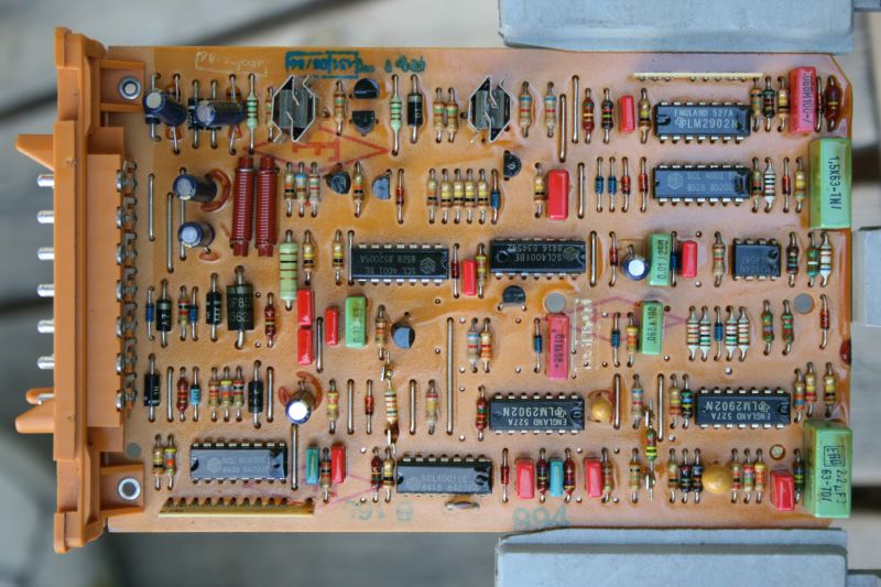
The circuit of the electronic control module consists of discrete and analog electronics, coupled with a few digital components. Microcontroller-controlled cruise control modules were only installed from 1/1987 on. Thus, the error in my two cruise control modules should be found and fixed.
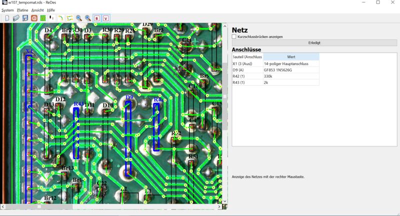
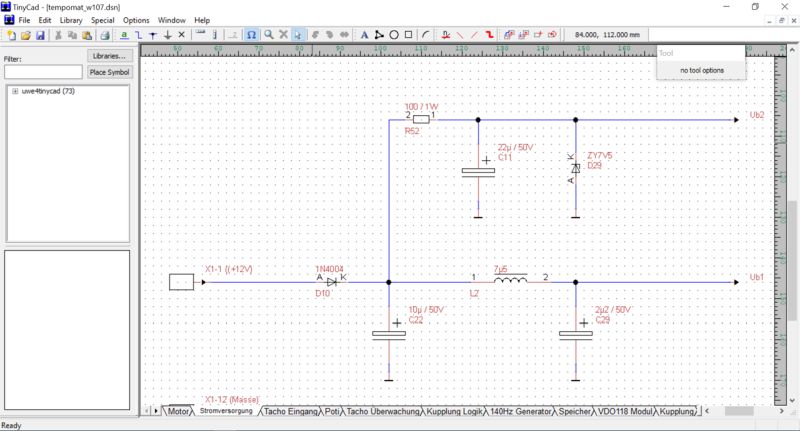
In order not to poke around in the fog, a circuit diagram needs to be available. The circuit diagram provided by the SL107 Club was incomplete and partly faulty. To support me in creating my own circuit diagram, I first developed a special software. Based on the board image, taken by a camera, I can draw in the components and re-paint the tracks. The software is able to generate a netlist, which is supporting me alot, when I have to draw the circuit diagram. The software can also handle wire bridges and create a parts list.
In sum, the preparation of the circuit diagram has taken several weeks. Nevertheless, the spent effort was worthwhile, because I now understand the electronic module in detail and so could quickly fix the errors.